Navigator IP Installation Wiring Diagrams and PCB overviewNavigator IP Wiring DiagramsPlease see following PDFs for your guide to installation.
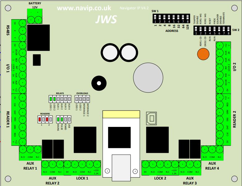
Navigator IP PCB Overview
Door A (left-hand side of PCB also known as Door 1) I/O 1 | READER 1 | AUX RELAY 1 |AUX RELAY 2 | LOCK1 Door B (right-hand side of PCB also known as Door 2) I/O 1 | READER 1 | AUX RELAY 1 |AUX RELAY 2 | LOCK1 Other ConnectionsLAN: Main LAN connection (bottom centre of PCB) Battery: For connection of Sealed Lead Acid battery, observe the polarity RS485: For RS485 Networks DIP SwitchesSW1 (Controller Addresses) SW2 LEDSRelays Overload Readers1 Door A - Red: Lock Engaged / Green: Lock Released 2 Door B - Red: Lock Engaged / Green: Lock Released MainMains: Primary incoming power (Normally ON) Pulse: System Heatbeat (Normally FLASHING) RS485: Activity on RS485 Network (Normally FLICKERING when an RS485 network is attached) USB: When unit is being programmed via USB (Normally FLICKERING when an USB lead is attached) | |||||||||||||


